Scripting electronic with Raspberry Pi Pico and MicroPython
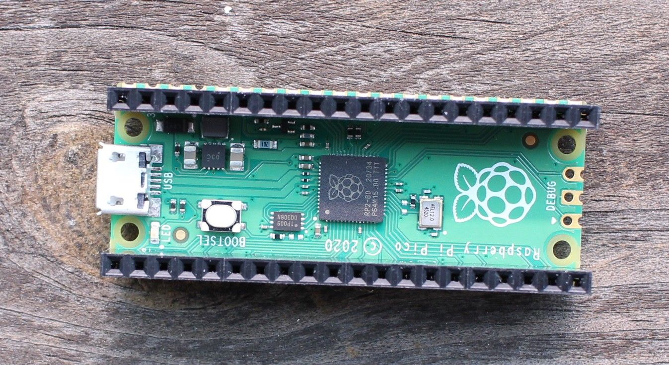
Raspberry Pi Pico is a board from the Raspberry Pi foundation. It's based on RP2040 microcontroller that provides 26 GPIO allowing us to control various electronic components at low cost and very low power consumption. Lets go over some of such components.
Getting started
In this tutorial I will be scripting electronics connected to the Pi Pico with MicroPython. Visit official getting started guide for instructions on how to use MicroPython with this board.
Note that Pi Pico does not come with goldpins soldered so you will have to get and solder them yourself or look for other board with RP2040 chip that is ready to use.
MicroPython shell - REPL
Quick and easy way to interact with MicroPython is to use REPL (Read Evaluate Print Loop) - a shell where you can write MicroPython code and watch it being executed. It's not best for writing larger or permanent chunks of code but it's handy to get started.
Establishing serial connection with REPL on Linux, macOS, Windows and Android
To use REPL we have to connect to the device via a serial connection. This can be done by hand from a shell/terminal or via Thonny editor. Windows, macOS and Linux users should just use Thonny as it's the easiest way.
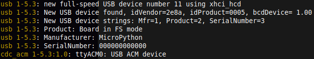
Connect the board to a PC and then establish the connection. For Linux we can use:
By default the board should appear as /dev/ttyACM0 device but if you have other serial devices connected it may be a different number. You can check dmesg logs after connecting the board to see what label it got from the dmesg
command logs:
On macOS it will have a different label but you should be able to find the label like so:
And then connect
To close screen connection (detach) press CTRL + A and then CTRL + D.
On Windows you can list connected serial devices by executing in cmd.exe (windows terminal):
Then you can try using third party app PuTTy to connect to Pi Pico.
Android options are limited - some devices will ship with Android build that has serial drivers and gives you enough permissions to use a serial connections. On top of that you need USB-OTG or Host USB port (common but not guaranteed on every device). You can try applications like Serial USB Terminal to see if you device supports this feature.
ChromeOS does allow installing Debian packages as well as using Python (Thonny can be installed as Python package) but at the time of writing this article Pi Pico isn't yet whitelisted for USB pass-through.
Using Thonny
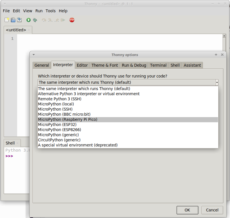
Thonny is a Python IDE (code editor) that supports MicroPython and REPL. It's available for Linux, macOS and Windows and takes all of the serial connection hassle unnecessary. If you can use Thonny for all of your MicroPython programming.
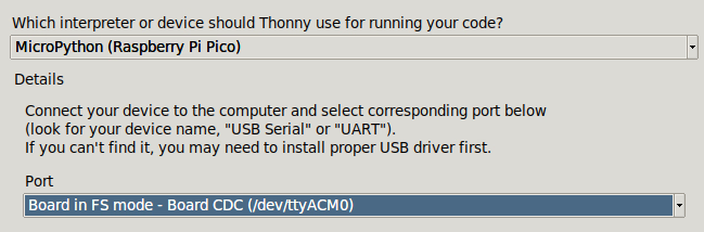
Run the app, then from top menu select Tools -> Options -> Interpreter. Select MicroPython for Pi Pico, then serial port the board uses and we should be good to go:
Thonny offers REPL access while main area can be used to write scripts that either can be executed or saved and sent to the board. When you power the board MicroPython will boot and will start looking for a file called main.py and if it finds it it will execute it - this is a way to keep the board programmed after disconnecting it from PC and using it stand-alone.
Working with REPL
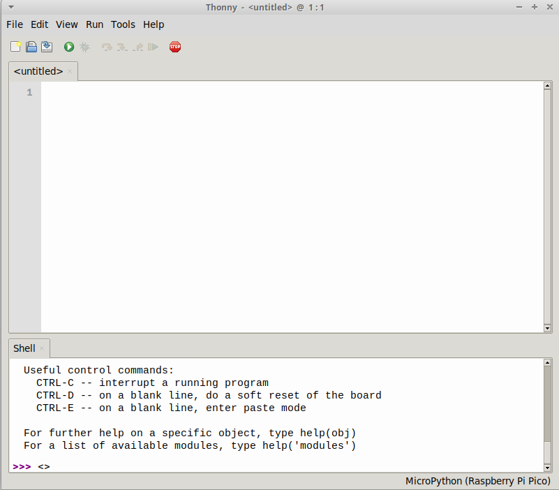
If you established the connection try writing help() in the shell window. You should see a response like this:
Welcome to MicroPython!

For online help please visit https://micropython.org/help/.

For access to the hardware use the 'machine' module.  RP2 specific commands
are in the 'rp2' module.

Quick overview of some objects:
  machine.Pin(pin) -- get a pin, eg machine.Pin(0)
  machine.Pin(pin, m, [p]) -- get a pin and configure it for IO mode m, pull mode p
    methods: init(..), value([v]), high(), low(), irq(handler)
  machine.ADC(pin) -- make an analog object from a pin
    methods: read_u16()
  machine.PWM(pin) -- make a PWM object from a pin
    methods: deinit(), freq([f]), duty_u16([d]), duty_ns([d])
  machine.I2C(id) -- create an I2C object (id=0,1)
    methods: readfrom(addr, buf, stop=True), writeto(addr, buf, stop=True)
             readfrom_mem(addr, memaddr, arg), writeto_mem(addr, memaddr, arg)
  machine.SPI(id, baudrate=1000000) -- create an SPI object (id=0,1)
    methods: read(nbytes, write=0x00), write(buf), write_readinto(wr_buf, rd_buf)
  machine.Timer(freq, callback) -- create a software timer object
    eg: machine.Timer(freq=1, callback=lambda t:print(t))

Pins are numbered 0-29, and 26-29 have ADC capabilities
Pin IO modes are: Pin.IN, Pin.OUT, Pin.ALT
Pin pull modes are: Pin.PULL_UP, Pin.PULL_DOWN

Useful control commands:
  CTRL-C -- interrupt a running program
  CTRL-D -- on a blank line, do a soft reset of the board
  CTRL-E -- on a blank line, enter paste mode

For further help on a specific object, type help(obj)
For a list of available modules, type help('modules')
To blink an on-board LED you can write such simple code:
from machine import Pin

led = Pin(25,Pin.OUT)
led.high()
This is an example of MicroPython code. It has it own custom modules like machine
. We import Pin class that handles simple GPIO pin actions. We set it to output and then put it on high
state - send current through it which causes a LED to light up. Similarly using .low() would turn it off.
You can script connected electronics from REPL which is a quick and easy solution. For more complicated or permanent code write scripts saved as files that then MicroPython can execute when the boards boot.
Scripting Pi Pico
If you want to execute a MicroPython script as you write it you can use Thonny. If you want to save your script on the board and make it run when the board is powered (while not connected to a PC) you can save it as a main.py
file.
Digital input/output
Simple digital input/output allows us to turn LEDs on, trigger switches or check if a button is pressed. We can start with the on-board LED that is assigned to pin 25:
import time

from machine import Pin


led = Pin(25,Pin.OUT)

for _ in range(10):
    led.high()
    time.sleep(1)
    led.low()
    time.sleep(1)
This script will blink the green LED on the board 10 times - we have a loop that:
- Sets the pin high (lights up a LED)
- Waits one second
- Sets the pin low (turns off the LED)
- Waits one second
- And repeat
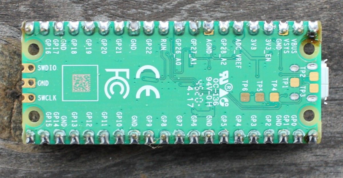
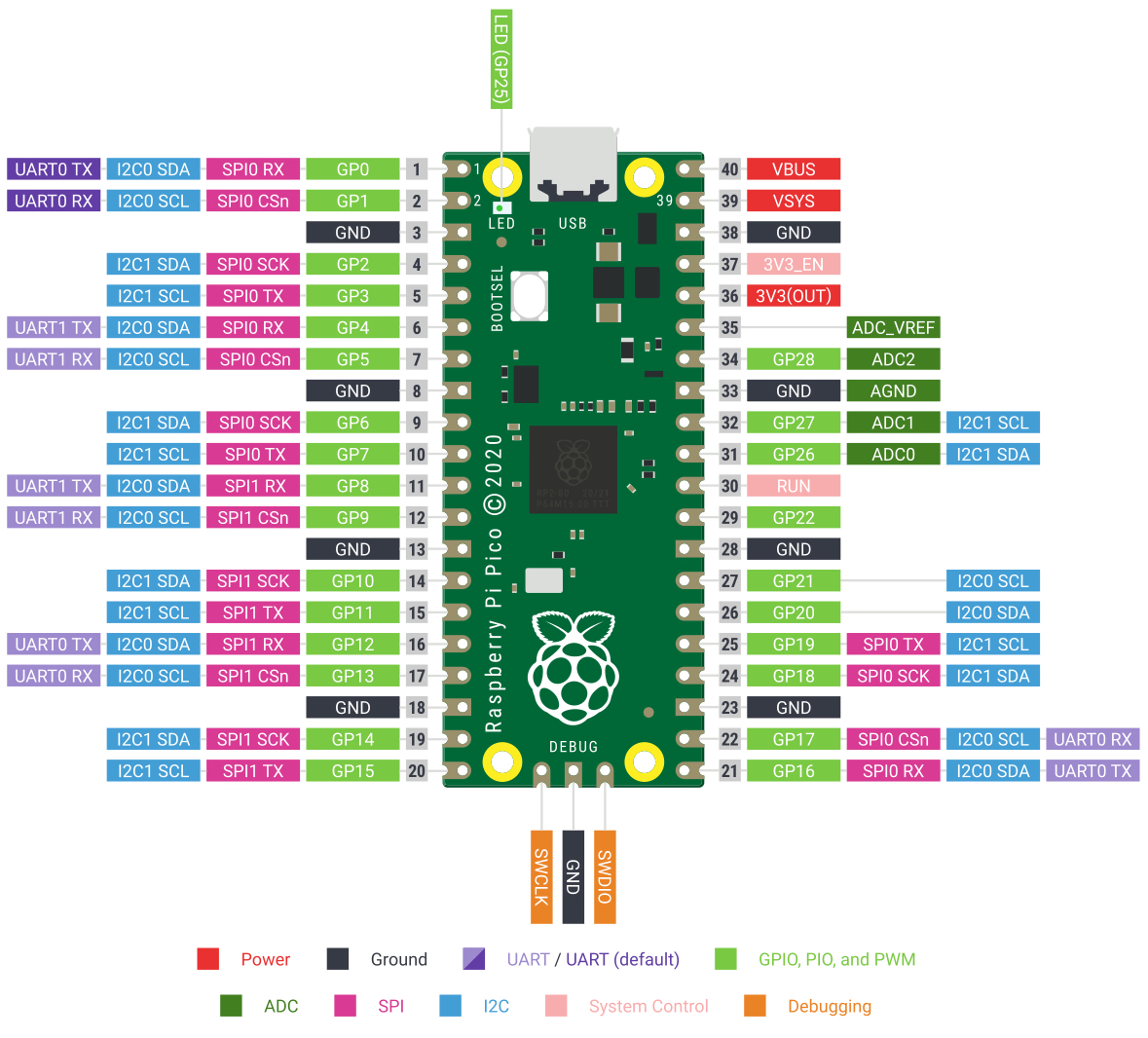
While working with Pi Pico you will check which pins offer features you need and what's their in-code labels and then you will use a matching MicroPython class that handles simple input/output or something more complex like SPI, I2C or UART. The bord layout is as follows:
So for example GP0 can be a output pin. We can recreat the LED setup with this pin connecting an LED to it and one of ground pins (GND):
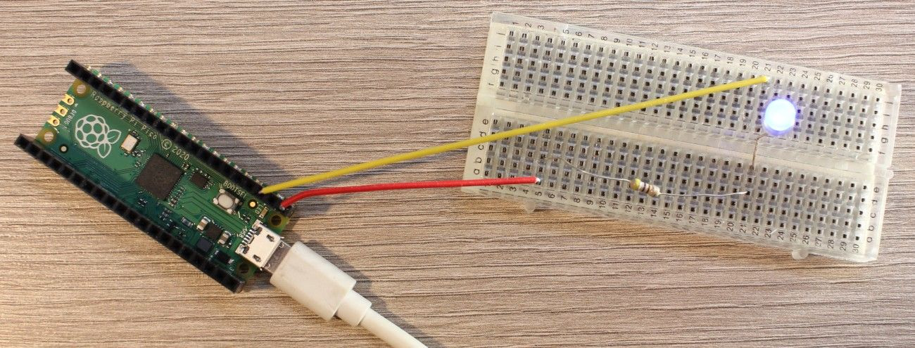
Here I also used a small resistor to limit the current as it's bit to high for LEDs (although if you don't have one you can still do this, just for a short moment).
As we used Pin GP0 we use that label in our code:
from machine import Pin


led = Pin(0,Pin.OUT)
led.high()
We can use output pins to control stepper motors that are used in high precision machines like 3D printers or focusers - they can move to specific positions repeatably and with high accuracy. Each position is a step thus the name.
For this example I used a low power 28BYJ-48 motor with ULN2003 control board - such kits are sold by various electronics shops. It's rated for 5V power and I/O but 3.3V Raspberry Pi Pico can handle it just fine. Note that more common motors found in devices will use much more power, often requiring 12V and those would require external power source to work when controlled by Pi Pico.
ULN2003 requires four output pins for controlling the motor. Power is provided by a pair of separate pins (USB 5V while for a short example even Pi Pico 3.3V will do):
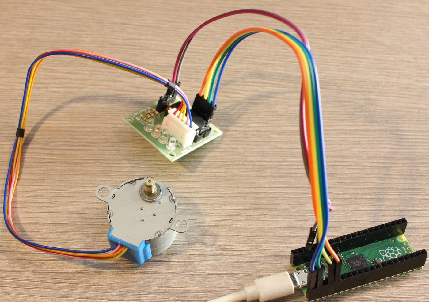
In the ULN2003 documentation we can find that to move the motor forward we have to put specific pins high for a moment: pin 1, then 1 and 2, then 2, then 2 and 3 and so on. In MicroPython it can be done like so:
First let start by configuring GP0, GP1, GP2 and GP3 pins for output:
import time

from machine import Pin


pin1 = Pin(0,Pin.OUT)
pin2 = Pin(1,Pin.OUT)
pin3 = Pin(2,Pin.OUT)
pin4 = Pin(3,Pin.OUT)

pins = [
    pin1, pin2, pin3, pin4,
]
Now let write those steps as lists of pins that must be high to move:
steps = [
    [pin1],
    [pin1, pin2],
    [pin2],
    [pin2, pin3],
    [pin3],
    [pin3, pin4],
    [pin4],
    [pin4, pin1],
]

current_step = 0
Based on which step we are in we can select which pins must be set high. After reaching the last element the sequence starts from the beginning:
while True:
    high_pins = steps[current_step]
    set_pins_low(pins)
    set_pins_high(high_pins)
    current_step += 1
    if current_step == len(steps):
        current_step = 0
    time.sleep(0.001)
Here we have an infinite loop that for current step sets all pins to low, then sets selected pins to high, increments step number and waits 0,001 of a second. The full code looks like so:
import time

from machine import Pin


pin1 = Pin(0,Pin.OUT)
pin2 = Pin(1,Pin.OUT)
pin3 = Pin(2,Pin.OUT)
pin4 = Pin(3,Pin.OUT)

pins = [
    pin1, pin2, pin3, pin4,
]

steps = [
    [pin1],
    [pin1, pin2],
    [pin2],
    [pin2, pin3],
    [pin3],
    [pin3, pin4],
    [pin4],
    [pin4, pin1],
]

current_step = 0


def set_pins_low(pins):
    [pin.low() for pin in pins]


def set_pins_high(pins):
    [pin.high() for pin in pins]


while True:
    high_pins = steps[current_step]
    set_pins_low(pins)
    set_pins_high(high_pins)
    current_step += 1
    if current_step == len(steps):
        current_step = 0
    time.sleep(0.001)
If you reverse the sequence order the motor will move in the opposite direction.
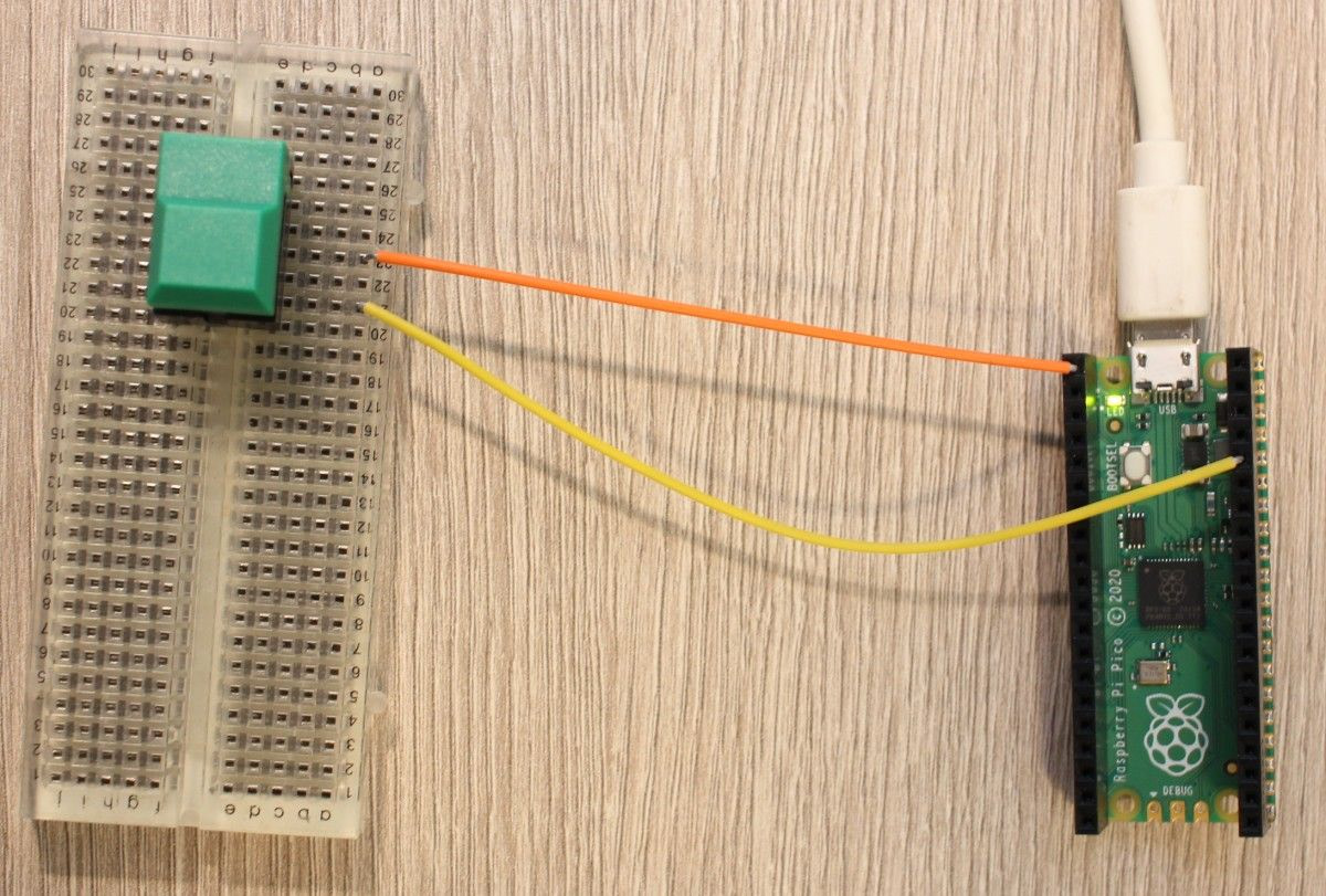
Digital input can be used to check for yes/no states - like if button is pressed or not:
import time

from machine import Pin


state = Pin(0,Pin.IN)
led = Pin(25,Pin.OUT)


while True:
    if state.value():
        led.high()
    else:
        led.low()
    time.sleep(0.1)
Digital input returns 1 if current is flowing through it and 0 if not. We can connect 3.3V pin with GP0 via a button or other similar component. If the button is pressed and the circuit is closed the on-board LED should light up.
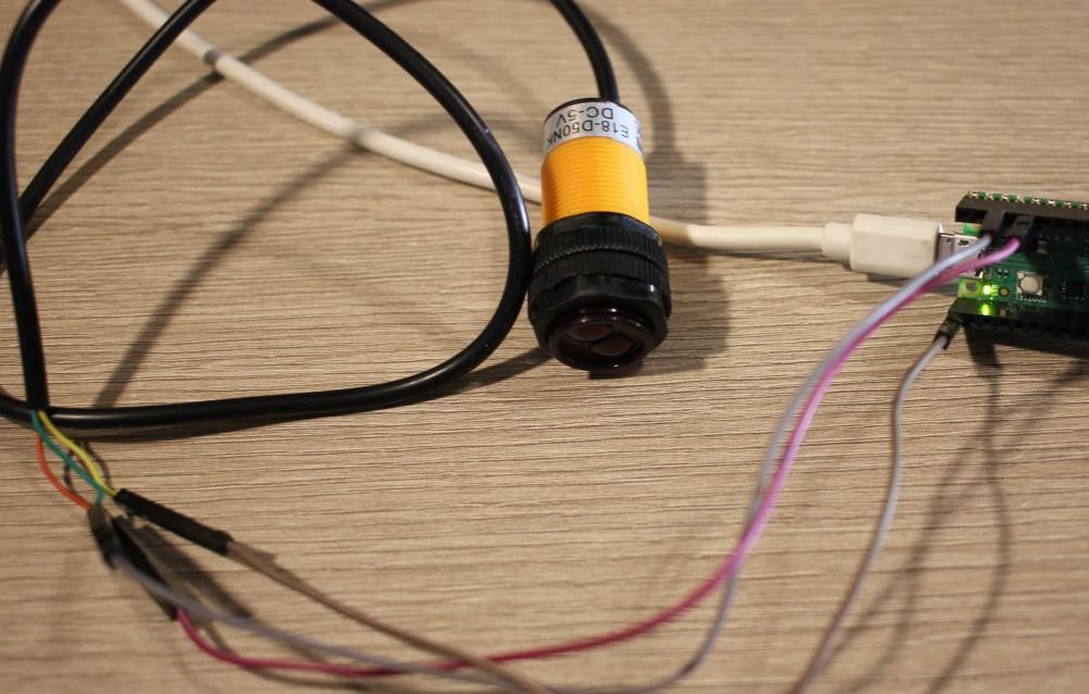
The E18-D50NK proximity sensor is quite simple - it has an infrared LED and a photodiode. The LED is constantly on and when you get close enough to an obstacle enough light will be bounced back onto the photodiode to close the circuit and return 1 on the pin. This isn't that precise (depends on surface and ambient light) but it's a good example of GPIO input usage.
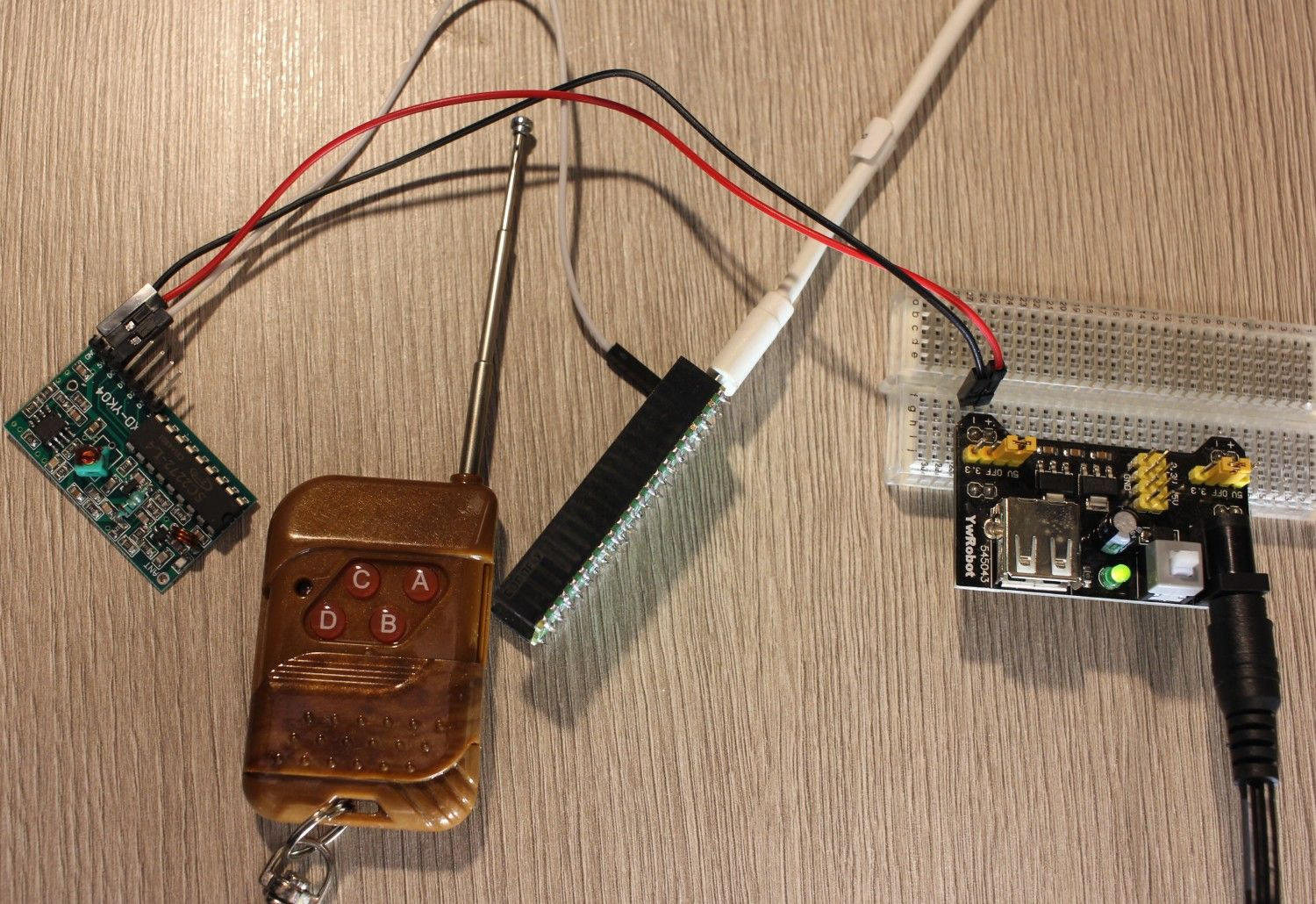
XD-YK04 remote toggle is one of cheap Chinese remote control switches. After pressing a button on the remote a digital pin on the receiver board will be set to low for few seconds - which Pi Pico GPIO Input can read. This can be used by Pi Pico to trigger some actions. Just note that such simple components may not offer the security and reliability needed when operating actual devices.
MicroPython also supports interrupts allowing you to wait for state change on the input pin without a need for a loop and constant value reading.
Pulse width modulation - PWM
PWM is a way to get an artificial analog output on a digital pin - getting a range of values from one pin and digital 0/1 operations. This can be used to control some electronics like servo motors, H-bridges for DC motors, LED dimming and alike.
MicroPython depending on microcontroller has some helper classes for servo handling but for Pi Pico there is none and using servo is bit tricky:
import machine


pin = machine.Pin(0)
pwm = machine.PWM(pin)
pwm.freq(50)

min = 0
max = 9000

for _ in range(10):
    for duty in range(min, max):
        pwm.duty_u16(duty)

    for duty in range(max, min, -1):
        pwm.duty_u16(duty)
GP0 pin is one of PWM capable so we configure it as such. Servos use 50Hz frequency while duty values will differ between servos (and what angle each value represents). And there are continuous servos as well, which are bit harder to code with this approach (hopefully someone will provide a smart helper library for servos).
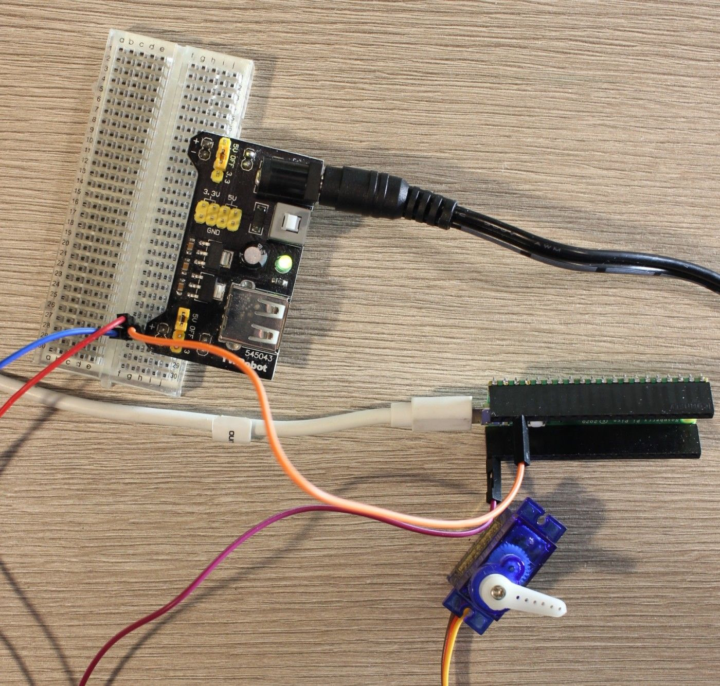
Note that you need external power for the servo as well as you have to connect Pi Pico ground to the power supply ground. Servos use 3-pin connection (PWM, VCC, GND) - PWM goes to the microcontroller while the other two to the servo power supply.
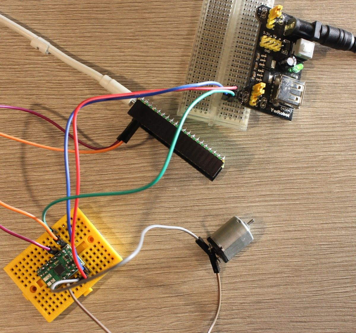
DC motors often found in various robots and toy vehicles can be controlled by H bridges - chips that take DC motor power and limit how much it gets based on PWM signal from the microcontroller - thus controlling the speed at which a DC motor rotates. You can buy a raw H bridge chip and design a circuit on your own or you can get ready to use boards with such chip - DC motor driver boards. I used Pololu DRV8833 but any such board operates on the same principle:
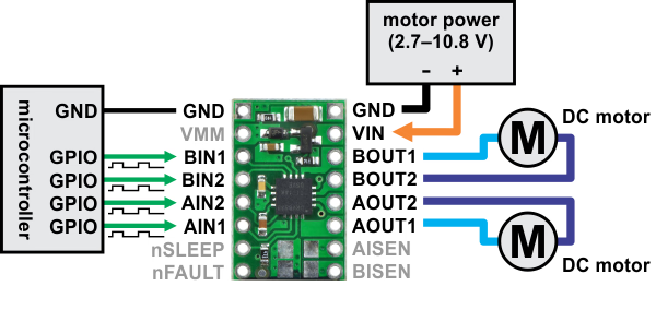
If you want to control one motor in both directions then you will need 2 PWM pins but for a one-direction example we can use just one:
import time
import machine


pin = machine.Pin(0)
pwm = machine.PWM(pin)
pwm.freq(50)


duties = [0, 32512, 48768, 65025]

for duty in duties:
    pwm.duty_u16(duty)
    time.sleep(4)


duties.reverse()

for duty in duties:
    pwm.duty_u16(duty)
    time.sleep(4)
Here we set high duty cycles up to max value to get max speed from the DC motor. This may differ a bit between board and motor.
UART - serial communication
Pi Pico has two UART interfaces. Serial (text) communication is often use to communicate with a more complex circuitry. Some multimeters and other measurement devices offer a serial connection where they send current measurement value. Even bigger devices like a PC (Raspberry Pi board) can use UART for debugging or simple communication.
MicroPython supports UART communication with an simple API:
uart = machine.UART(0, baudrate=9600)
# uart.write()
# uart.read()
Where 0
is the UART interface number you want to use (Pi Pico has 0 and 1). Baudrate can differ depending on which device you connect to.
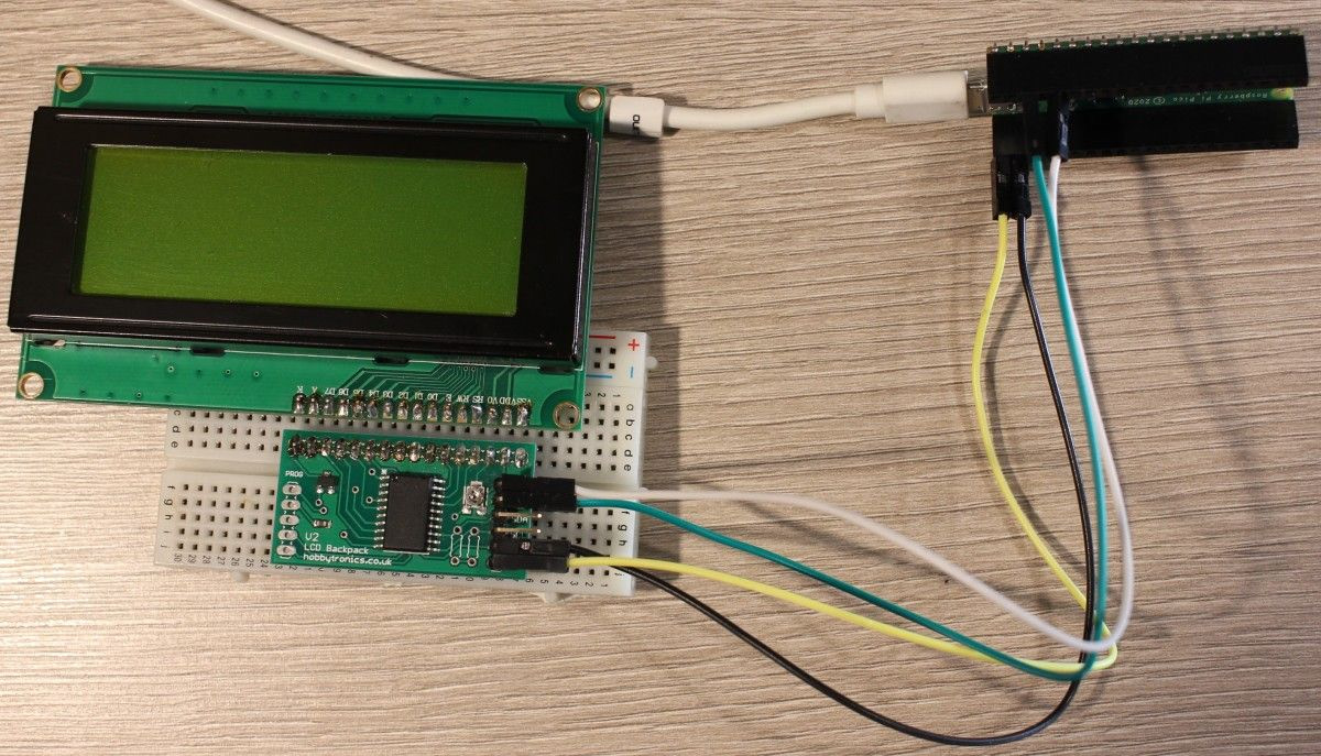
I've tried to used Hobbytronics LCD to Serial adapter and a LCD screen but sadly on Pi Pico it didn't worked even when working for USB-UART and PySerial code on PC (this could be related to how data is formatted?):
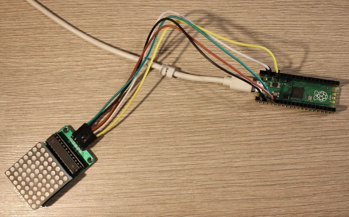
SPI communication
SPI is a simpler communication protocol yet it supports multiple devices which gets quite pin efficient. MAX7219 8x8 LED driver uses SPI communication and has MicroPython third party libraries, yet with Pi Pico something is not quite right as it doesn't work. I'll try to research SPI and UART problems and update this section when things get resolved.
Resources
For MicroPython you can check Pi Pico SDK documentation. Aside of that there likely will be libraries popping up on Github and support on the Pi forums.
CircuitPython
CircuitPython is Adafruit fork of MicroPython. It promises a more consistent API across boards, easier introduction process and much better high level support for scripting various components.
For Pi Pico version of CircuitPython check learn.adafruit.com.
Comment article