Using GPIO, USB and HDMI on the PYNQ-Z2 board
In this article I'll go over some additional PYNQ-Z2 features like GPIO, USB and HDMI functionalities. If you are new to PYNQ FPGA accelerated edge-computing platform then you can go check out my introduction tutorial.
USB-UART
USB port on the PYNQ-Z2 board is connected to the CPU (Processing System - PS) so we can use it like a regular USB host port. One of ways to use it is to connect a USB-Serial adapter or a microcontroller board if we need such features.
Although PYNQ-Z2 does have GPIO headers it may be beneficial to move more complex I/O functionality of this type to a dedicated microcontroller board - like one based on MicroPython, CircuitPython, Zerynth, TinkerForge or Arduino - especially when we are using more complex components that use dedicated libraries (and those are often provided to the most popular platforms only).
Serial, RS232 and alike are also an industry standard for connecting to and controlling various devices. It may be that your camera or other device providing video or audio for PYNQ board has such connector and if so we could use USB-serial adapter to connect to it and control it alongside our data processing code - turn it on via bit of Python code instead of manually pressing a button.
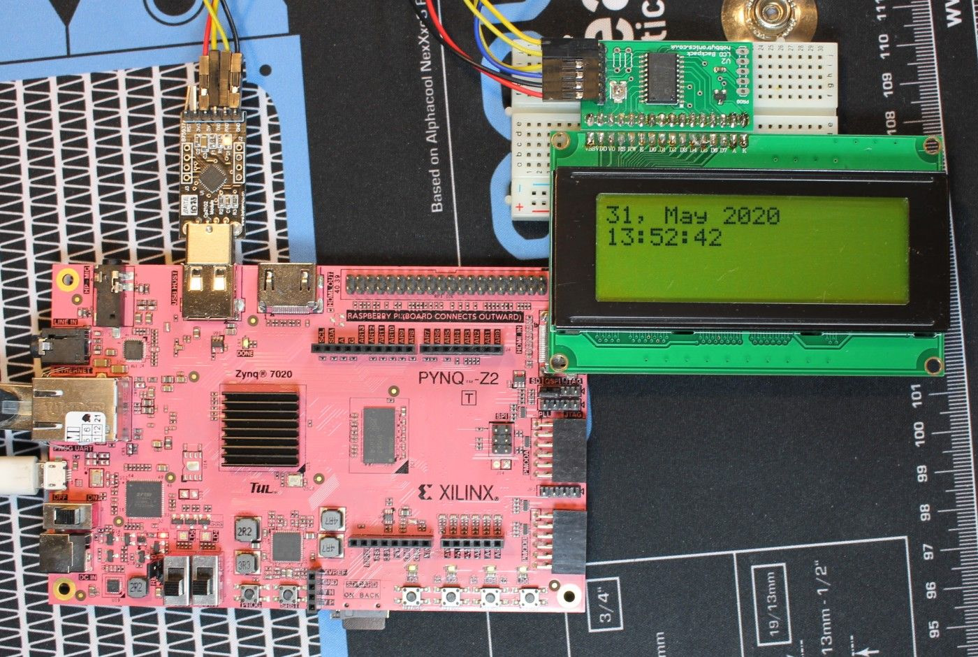
For this example I used a generic USB-UART adapter and a LCD display with a Hobbytronics serial controller:
Power your board, connect to it via SSH or via serial connection:
Install pySerial library:
Now you can run showcased below code either as file via the console or in the Jupyter notebook. First off lets start with a handy class that will make it easier to operate on the display - this code is based on the API provided by the Hobbytronics controller:
import time

from datetime import datetime

import serial


class LCD:
    END = chr(0xFF)

    def __init__(self, device, rows, columns):
        self.commands = {
            'display_string': chr(1),
            'set_cursor_position': chr(2),
            'clear_line': chr(3),
            'clear': chr(4),
            'set_lcd_type': chr(5),
            'backlight': chr(7)
        }
        self.device = device
        self.rows = rows
        self.columns = columns
        self.connection = None

    def configure(self):
        self.connection = serial.Serial(
            self.device, 9600, timeout=5, bytesize=serial.EIGHTBITS, parity=serial.PARITY_NONE,
            stopbits=serial.STOPBITS_ONE, xonxoff=False)
        time.sleep(1)
        self.execute_command('set_lcd_type', chr(self.rows) + chr(self.columns))
        self.clear()

    def clear(self):
        self.execute_command('clear', '')

    def clear_line(self, line):
        self.execute_command('clear_line', chr(line))

    def set_backlight(self, brightness):
        self.execute_command('backlight', chr(brightness))

    def set_cursor_position(self, row, column):
        self.execute_command('set_cursor_position', chr(row) + chr(column))

    def display_string(self, string):
        self.execute_command('display_string', string)

    def close(self):
        self.connection.close()

    def execute_command(self, command, payload):
        full_command = self.commands[command] + payload + self.END
        full_command = full_command.encode('iso-8859-1')
        self.connection.write(full_command)
And example usage - a clock/date display:
lcd = LCD("/dev/ttyUSB0", rows=2, columns=16)  # change to your serial device ID if needed
lcd.configure()
lcd.set_backlight(25)

while True:
    day = datetime.now().strftime('%d, %b %Y')
    current_time = datetime.now().strftime('%H:%M:%S')

    lcd.set_cursor_position(1, 1)
    lcd.display_string(day)
    lcd.set_cursor_position(2, 1)
    lcd.display_string(current_time)
    time.sleep(1)
This code will run on PYNQ board or on your PC, laptop, whatever that can run pyserial library and has a USB port.
For fun you could use such LCD to display PYNQ resource usage or system logs.
GPIO - running a stepper motor
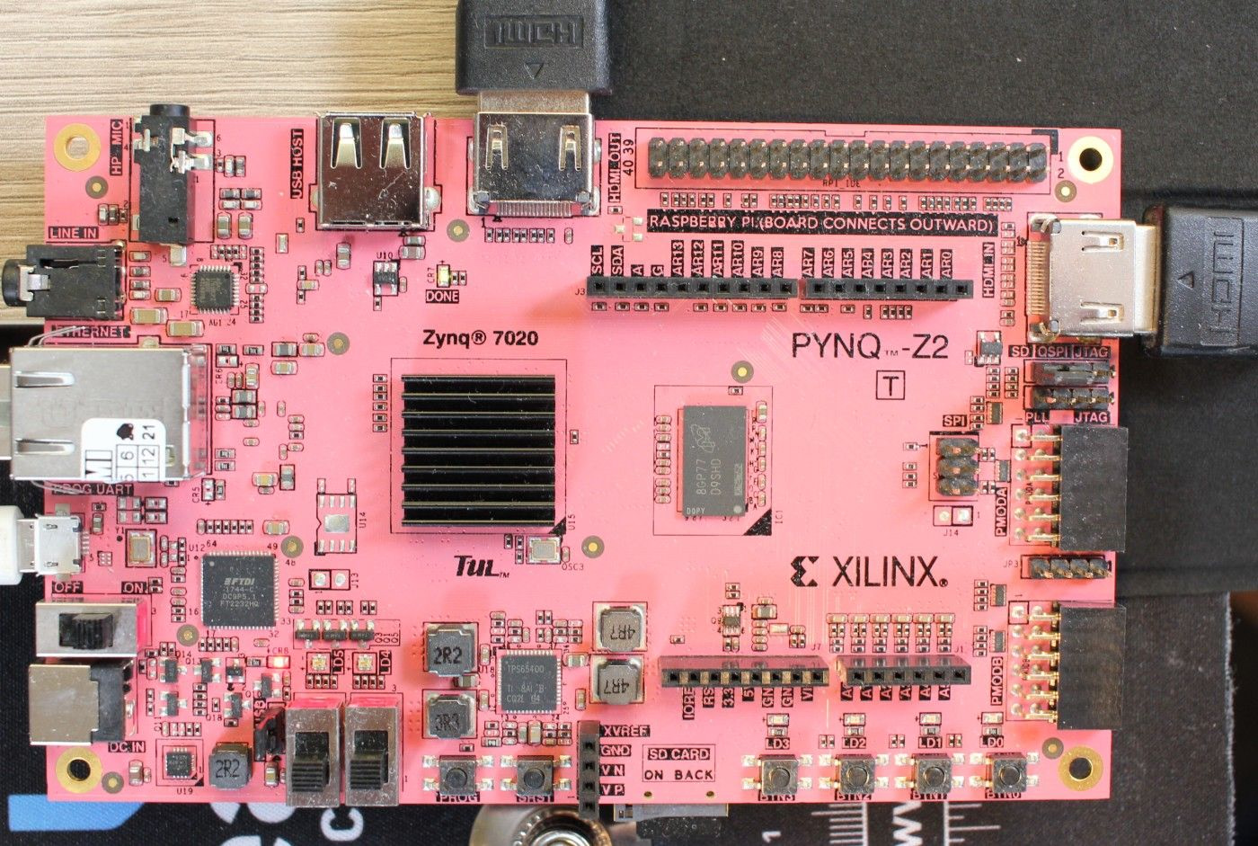
So now lets try to use PYNQ-Z2 GPIO that is provided on the board. The layout of the headers may look like Arduino Uno or Raspberry Pi but functionality may change based on overlay (FPGA configuration) used.
For digital pin functionality we can use arduino_io.Arduino_IO module. Digital pin can be either high
(1) or low
(0). As stated in the documentation the A0 and subsequent pins are digital pins number 14 and up.
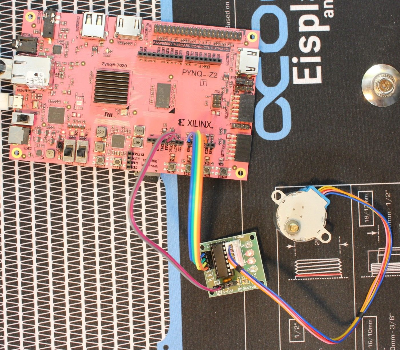
For this example I used a low power Chinese 28BYJ-48 stepper motor with ULN2003 controller. This kit is easy to get, although you can use a LED + resistor to test this GPIO as well.
To drive this stepper motor you need 4 GPIO that will turn high in specific order over and over again.
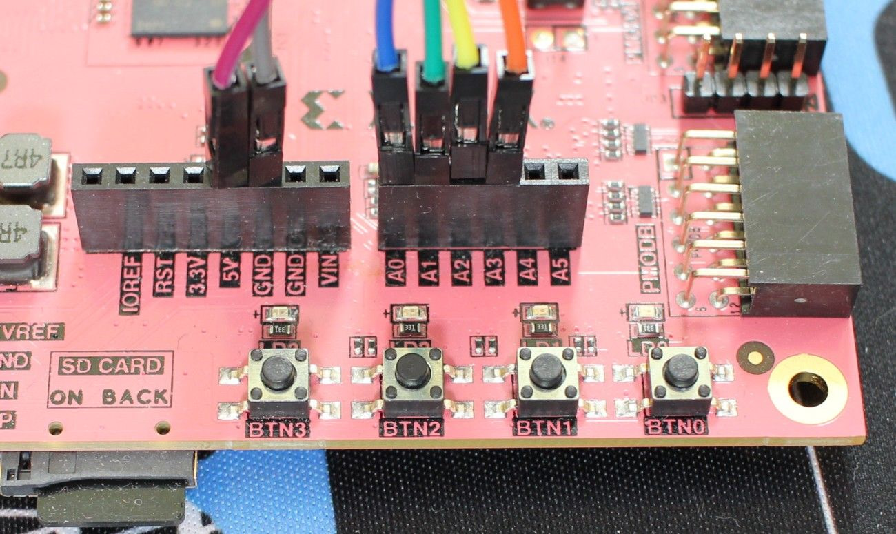
On the PYNQ-Z2 image you can find few example notebooks in base/arduino folder. The first thing to do wherever you are using Arduino_IO or other Arduino module is to configure given pins for that purpose:
import time

from pynq.overlays.base import BaseOverlay
from pynq.lib.arduino import arduino_io

base = BaseOverlay('base.bit')

p1 = arduino_io.Arduino_IO(base.iop_arduino.mb_info, 14, 'out')
p2 = arduino_io.Arduino_IO(base.iop_arduino.mb_info, 15, 'out')
p3 = arduino_io.Arduino_IO(base.iop_arduino.mb_info, 16, 'out')
p4 = arduino_io.Arduino_IO(base.iop_arduino.mb_info, 17, 'out')
Now we can play with pins high/low state to drive the motor:
def set_pins(pins, value):
    for pin in pins:
        pin.write(value)


steps = [
    [p1],
    [p1, p2],
    [p2],
    [p2, p3],
    [p3],
    [p3, p4],
    [p4],
    [p1, p4]
]

pins = [p1, p2, p3, p4]
current_step = 0


for i in range(0, 4000):
    high_pins = steps[current_step]
    set_pins(pins, 0)
    set_pins(high_pins, 1)
    current_step += 1
    if current_step == len(steps):
        current_step = 0
time.sleep(0.01)You can check examples in the Jupyter notebook as well as bootcamp notebooks for more examples.
GPIO - emulating button presses on an external device
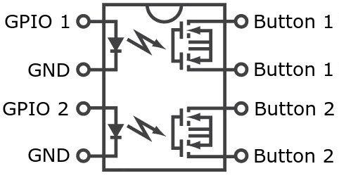
If you are running a audio/video project with PYNQ and the camera doesn't have a serial port then you can still control it via digital GPIO. What can make the magic happen is a optocoupler or a small SSR - solid state relay… and the camera has to have physical buttons used to control or power it on/off.
SSR or an optocoupler will close a circuit when current is put to the control side. Both circuits are separated as the control circuit actually turns a small LED on while the load side reacts to light and closes the circuit. Thanks to this both control and load sides can operate on different voltages.
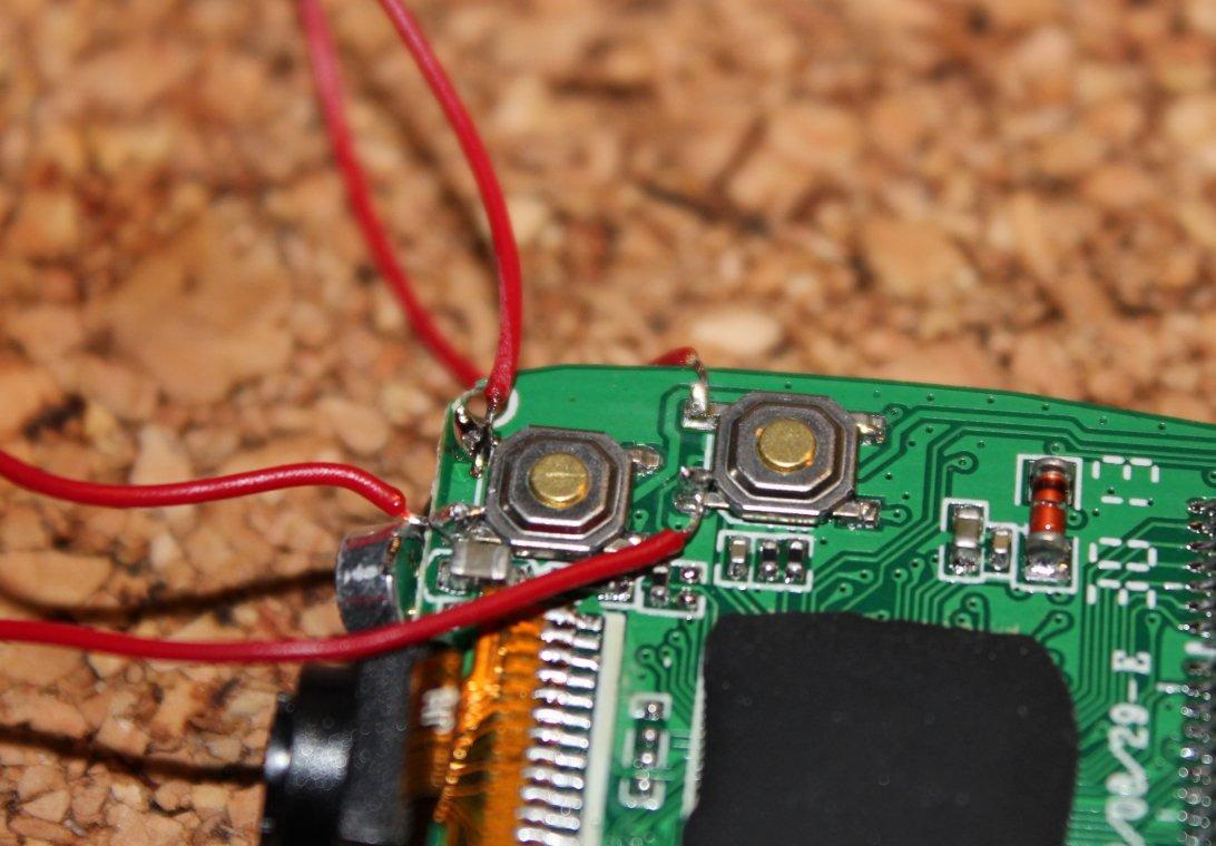
The camera or other device you want to control will likely have physical buttons and you can solder wires to both sides of a button and connect it to the load
side of a SSR/optocoupler. The line will not be closed by default - button not pressed. To close it and emulate a button press the control side pin has to be set to high similarly how it was done in the stepper motor example - set it high for a second or two and the set it low - that should give you a button press effect without actually pressing the button.
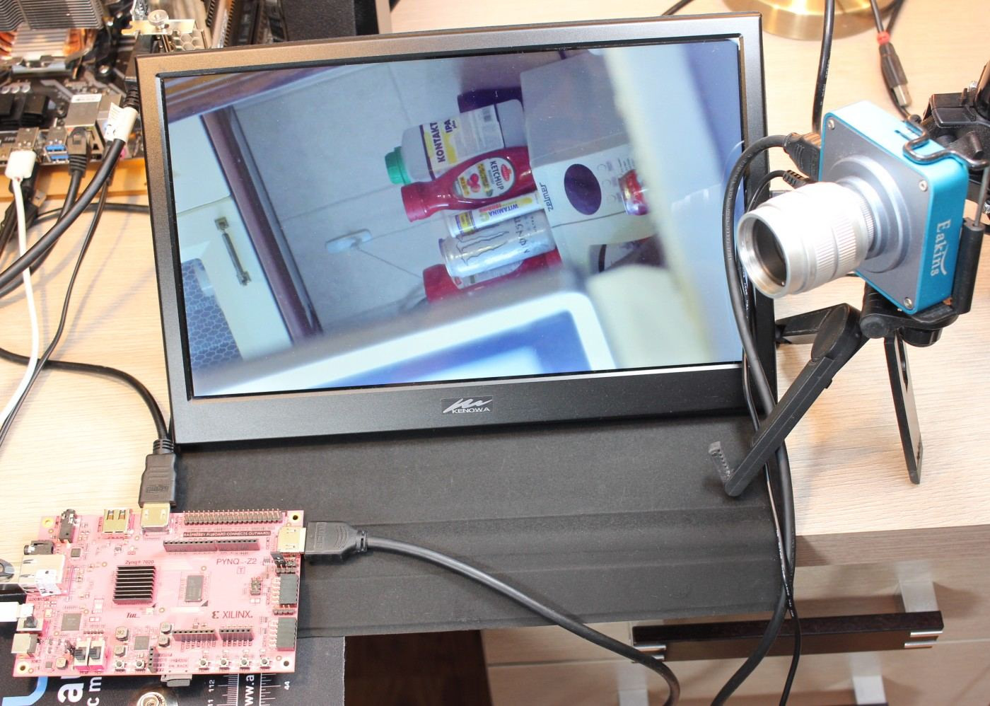
HDMI - working with cameras
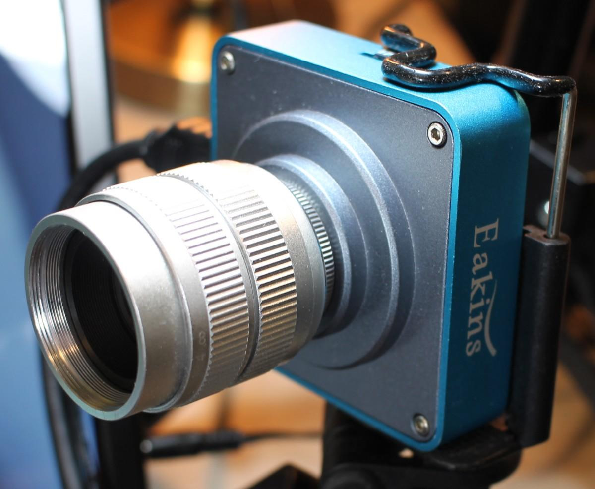
The HDMI ports on the PYNQ-Z2 board are connected to the FPGA part (PL - programmable logic) and can be used for HDMI stream processing. You will need a camera with HDMI out and a HDMI display to see the end result. For PYNQ-Z2 a 720p 30FPS camera is advised although my 1080p 60FPS camera also managed to work, although processing was done with half the frame rate.
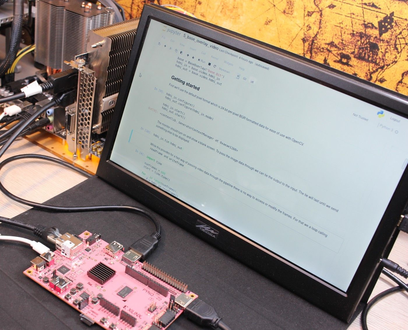
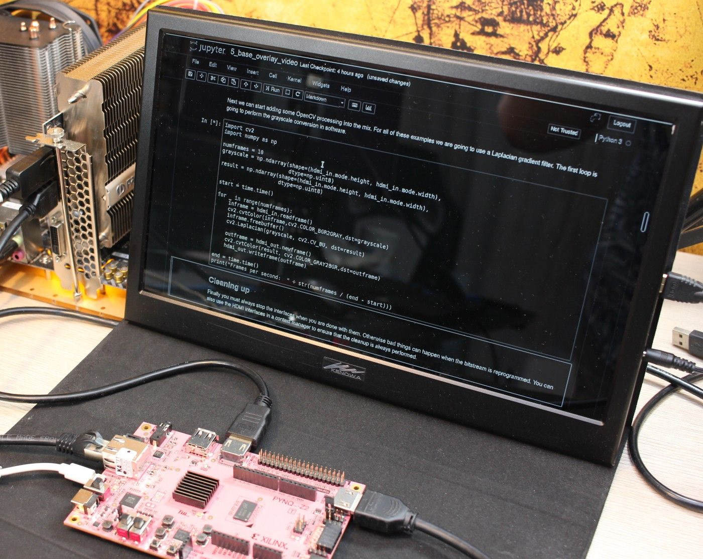
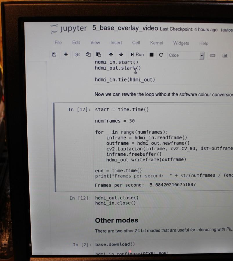
The default image for PYNQ-Z2 has a set of notebooks showcasing HDMI processing capabilities. First of all there is getting_started/5_base_overlay_video.ipynb notebook that showcases HDMI handling and basic processing.
Next you can check base/video notebooks that showcase USB webcam and HDMI camera processing features. Also element14 webinars showcase how to create a custom overlay (FPGA configuration) in Vivado with specific accelerated processing pipeline - but that's getting close to FPGA programming.
HDMI - working with PC HDMI input
If you don't have a camera or want specific input image (like a list of faces for a face detection algorithm) you can use a HDMI output from a PC/laptop. Just connect it to the input on the PYNQ-Z2 board and connect PYNQ output to the HDMI display. To be able to use the PC you while feeding PYNQ with the video stream you will have to configure it to mirror image on two displays (laptop screen + PYNQ or PC with 2 displays, one directly connected to it and the other via PYNQ). With a mirror setup the resolution may be set to like 720p due to PYNQ board not handling high resolutions.
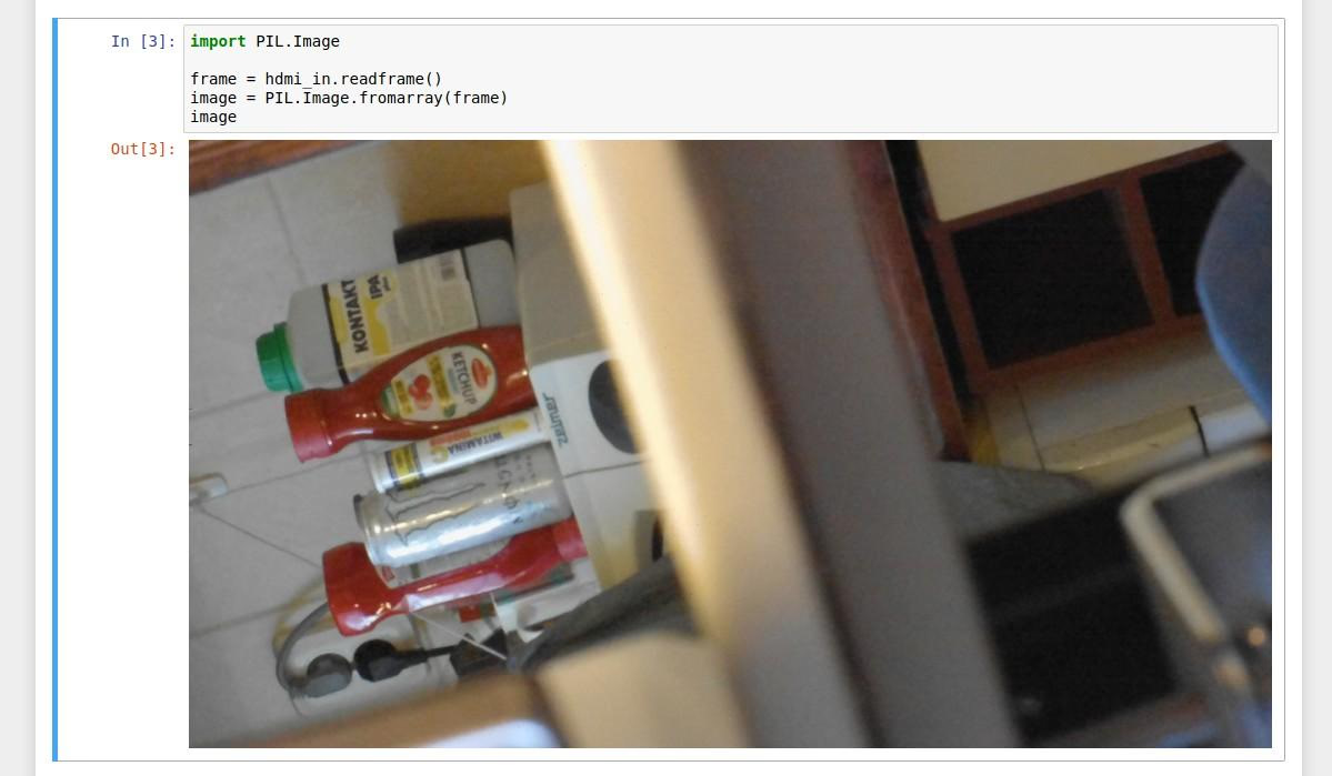
You can either open specific image or a video in a browser or locally and then execute the code in the Jupyter notebook that will do some actions on the HDMI video stream.
Comment article