Updating pyboard firmware for latest MicroPython features and fixes
Pyboard can handle analog sensors and precise PWM control, but to get that we have to use one of the latest firmwares. So let us update the firmware and test it with an analog joystick and PWM controlled DC motor board.
Firmware update
The update process is described on the wiki. You need a Linux with dfu-util which ought to be in the repository.
As the descriptions says you have to disconnect everything from pyboard and the board itself from any power. Then connect DFU with 3.3V and connect the board to the PC.

Then update it with:
When you see done parsing DfuSe file
the update will be complete and you can disconnect pyboard from the PC and remove the pin connection.
Analog joystick
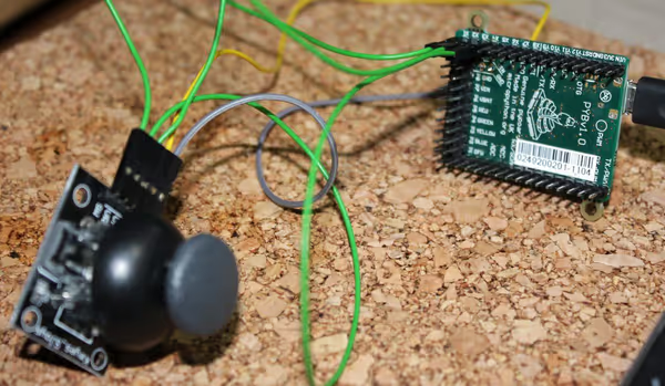
Analog joystick consists of two potentiometers and one push button. The potentiometers can be handled by ADC, while the button with plain digital GPIO pin. Here is a handy class I wrote to handle such joysticks:
import pyb


class Joystick:
    def __init__(self, x_axis_pin, y_axis_pin, button_pin):
        self.x_axis = pyb.ADC(x_axis_pin)
        self.y_axis = pyb.ADC(y_axis_pin)
        self.button = pyb.Pin(button_pin, pyb.Pin.IN, pull=pyb.Pin.PULL_UP)

    def get_state(self):
        return {
            'x': self.x_axis.read(),
            'y': self.y_axis.read(),
            'button': self.button.value()
        }
I've used X1,2,3 pins for the joystick and then in the pyboard REPL (shell) I used that class like so:
from joystick import *
j = Joystick('X3', 'X2', 'X1')
j.get_state()
#{'x': 2913, 'button': 1, 'y': 2867}
while True:
    pyb.delay(150)
    print(j.get_state())
For the X and Y axis values (potentiometers) the ADC class is used which reads
a digitalized value of current that changes when potentiometer resistance changes due to gauge position change. The push button is used by Pin class. It has a pull-up configured as my joystick board seemed to need for the button state to be correctly determined. Note that between various joystick board returned values may differ (even a lot), and you must experimentally see what is the best value range of each axis and map it on your own scale, that later can be used to control something else.

Using Timer class to controll DC motors via PWM
In the previous article I've used Servo class to control a DC motor via DC motor controller board that uses PWM to set motor speed in given direction. It didn't allowed for easy control of the whole PWM range (like zero
for stop). Timer class allows that, although like so:
timer = pyb.Timer(2, freq=1000)
ch1 = timer.channel(1, pyb.Timer.PWM, pin=pyb.Pin.board.X1, pulse_width=20000)
At first we create a timer with it's ID and frequency. Next we create a channel, set it to PWM and select pin for it. Setting value to pulse_width determines how fast the motor will run. After creating the channel object you can use the pulse_width method to set it with values you like to stop or move the motor with some speed. Best value range also must be discovered experimentally.
Comment article