Scripting LCD on Wio Terminal with ArduPy
One of Wio Terminal key features is the LCD display. It can be used to provide a graphical interface for your device. In this tutorial I'll go over using the LCD in MicroPython with ArduPy.
ArduPy on Wio Terminal
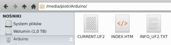
To get ArduPy running on Wio Terminal we have to flash it with latest ArduPy build. It's described on wiki and in short it's like so:
- Enter bootloader mode by pressing the power button down two times quickly - this will mount Wio Terminal like if it was a flash drive
- Copy the UF2 ArduPy file - the device will reconnect shortly in ArduPy mode
Optionally you can install aip on your local machine:
This tool can help managing Wio Terminal, especially for ArduPy.
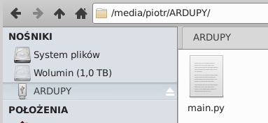
When we are in ArduPy mode we have typical for MicroPython main.py file - code there will be executed on board boot.
Scripting LCD via ArduPy
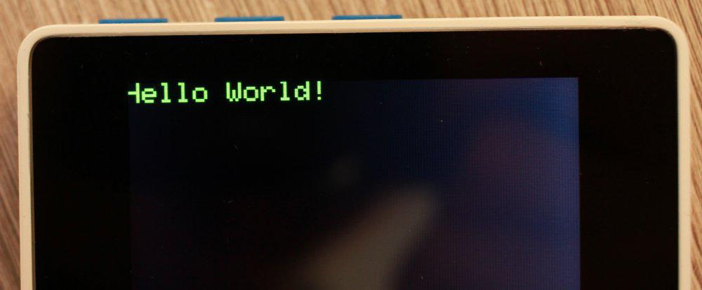
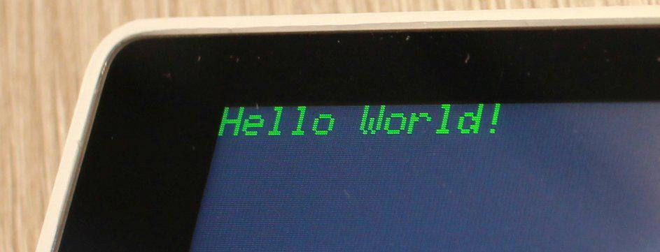
There is a API reference for the LCD and a simple Hello World looks like so:
from machine import LCD
lcd = LCD()                            # Initialize LCD and turn the backlight
lcd.fillScreen(lcd.color.BLACK)        # Fill the LCD screen with color black
lcd.setTextSize(2)
lcd.setTextColor(lcd.color.WHITE)
lcd.drawString("Hello World!", 0, 0)
To use the LCD you just initialize it and then you can draw at specified coordinates (LCD has 320x240 pixels).
You can also draw various geometrical shapes like circles, triangles, rectangles or simple lines:
import time
from machine import LCD
lcd = LCD() # Initialize LCD and turn the backlight
lcd.fillScreen(lcd.color.BLACK) # Fill the LCD screen with color black
lcd.setTextSize(2)
lcd.setTextColor(lcd.color.WHITE)
x = 320
y = 240
x_start = 10
y_start = 5
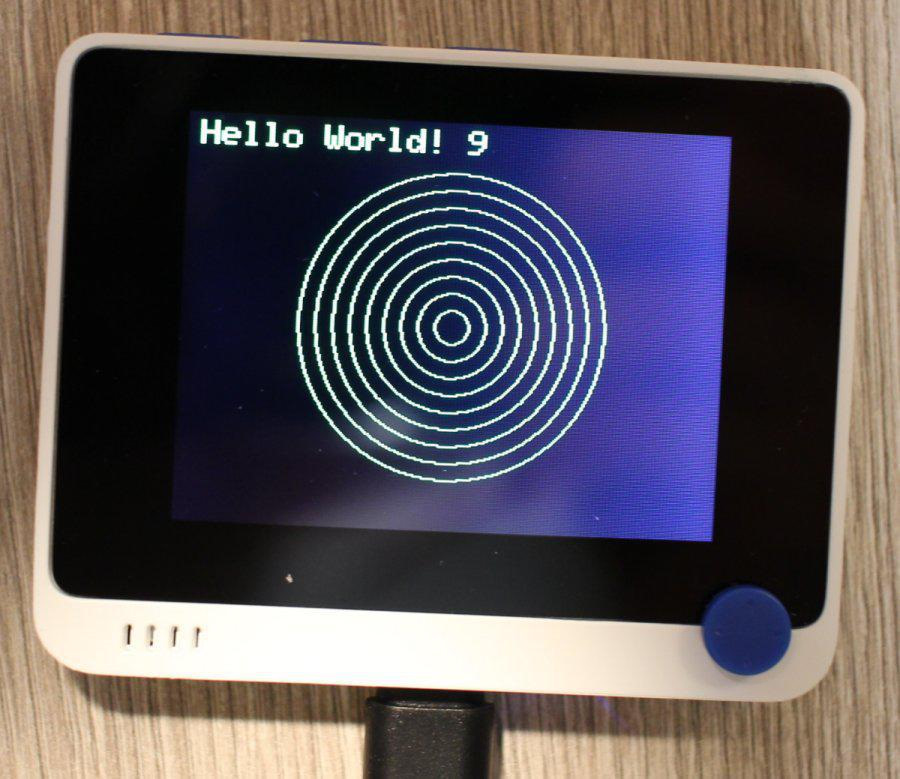
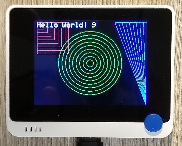
for i in range(1, 10):
lcd.drawString("Hello World! %s" % i, x_start, y_start)
lcd.drawCircle(int(x/2), int(y/2), int(10*i), lcd.color.GREEN)
lcd.drawRect(x_start, y_start, int(10*i), int(10*i), lcd.color.RED)
lcd.drawTriangle(x, y_start, int(x-20*i), y_start, x, y, lcd.color.BLUE)
time.sleep(1)Here in a for-loop we draw text and some geometrical shapes. Notice how text overwrites previous one as it's in the same spot while shapes draw bigger and bigger versions of themselves. To clear screen you would have to use fillScreen but that is quite expensive operation and for a short while the screen will be completely blank. In such cases the best way is to draw the static UI once and make the dynamic part in a way that it just over-draws itself without the need of full screen redraw.
Here is more advanced example with static and dynamic part. For static we want to draw borders around the screen and labels and for dynamic we want to display current radius and draw a circle for said radius:
import time

from machine import LCD

lcd = LCD()
lcd.fillScreen(lcd.color.BLACK)

x = 320
y = 240

x_start = 5
y_start = 5

x_max = x - int(x_start * 2)
y_max = y - int(y_start * 2)


class CircleApplication:
    LABEL_PADDING = 5
    SECOND_LINE = 50
    SECOND_COLUMN = 90

    def __init__(self, lcd):
        self.lcd = lcd

    def draw_ui(self):
        self._draw_borders()
        self._draw_labels()

    def _draw_borders(self):
        self.lcd.drawFastHLine(x_start, y_start, x_max - x_start, lcd.color.GREEN)
        self.lcd.drawFastHLine(x_start, y_start + self.SECOND_LINE, x_max - x_start, lcd.color.GREEN)
        self.lcd.drawFastHLine(x_start, y_max, x_max - x_start, lcd.color.GREEN)
        self.lcd.drawFastVLine(x_start, y_start, y_max - y_start, lcd.color.GREEN)
        self.lcd.drawFastVLine(x_max, y_start, y_max - y_start, lcd.color.GREEN)
        self.lcd.drawFastVLine(
            x_max - self.LABEL_PADDING - self.SECOND_COLUMN - self.LABEL_PADDING,
            y_start, self.SECOND_LINE, lcd.color.GREEN)

    def _draw_labels(self):
        self.lcd.setTextSize(1)
        self.lcd.setTextColor(lcd.color.WHITE)
        lcd.drawString('Loop index:', x_start + self.LABEL_PADDING, y_start + self.LABEL_PADDING)
        lcd.drawString(
            'Current radius:',
            x_max - self.LABEL_PADDING - self.SECOND_COLUMN,
            y_start + self.LABEL_PADDING,
        )

    def draw_circle(self, index):
        self._draw_loop_index(index)
        radius = self._get_radius(index)
        self._draw_radius(radius)
        self._draw_circle(radius)

    def _draw_loop_index(self, index):
        self.lcd.setTextSize(3)
        self.lcd.setTextColor(self.lcd.color.BLUE)
        self.lcd.drawString(
            str(index),
            x_start + 120,
            y_start + 15,
        )

    def _get_radius(self, index):
        return index * 15

    def _draw_radius(self, radius):
        self.lcd.drawString(
            str(radius),
            x_max - int(self.SECOND_COLUMN / 2) - 25,
            27,
        )

    def _draw_circle(self, radius):
        self.lcd.drawCircle(int((x - + self.SECOND_LINE)/2), int(y/2), radius, self.lcd.color.GREEN)


c = CircleApplication(lcd)
c.draw_ui()
c.draw_circle(2)
draw_ui method draws the static part while draw_circle draws the dynamic part for given index (like in the for-loop example before). A lot of this code is just getting X/Y coordinates. It could potentially be replace by drawing a bitmap (BMP graphics file) which would be easier to draw and update in the future.
In this example we get subsequent circles. But we can also clear the previous circle by drawing it in black
when next circle is being drawn:
def _draw_current_circle(self, radius, index):
        self._draw_circle(radius, self.lcd.color.GREEN)
        if index > 1:
            self._draw_circle(self._get_radius(index - 1), self.lcd.color.BLACK)

    def _draw_circle(self, radius, color):
self.lcd.drawCircle(int(x/2), int(y/2) + int(self.SECOND_LINE / 2), radius, color)Using built-in buttons
Wio Terminal has 3 top buttons. Their IDs are available in machine.Map
module:
from machine import Pin
from machine import Map

a = Pin(Map.WIO_KEY_A, Pin.IN)
b = Pin(Map.WIO_KEY_B, Pin.IN)
This is typical MicroPython code and API. However ArduPy lacks pyb
module and the Pin
class doesn't have irq
method - no support for interrupts on buttons. So to handle actions on button press we have to use a while loop.
Let start with the CircleApplication
class (with few modifications to circle drawing):
import time

from machine import LCD
from machine import Pin
from machine import Map

lcd = LCD()                            # Initialize LCD and turn the backlight
lcd.fillScreen(lcd.color.BLACK)        # Fill the LCD screen with color black

x = 320
y = 240

x_start = 5
y_start = 5

x_max = x - int(x_start * 2)
y_max = y - int(y_start * 2)


class CircleApplication:
    LABEL_PADDING = 5
    SECOND_LINE = 50
    SECOND_COLUMN = 90

    def __init__(self, lcd):
        self.lcd = lcd

    def draw_ui(self):
        self._draw_borders()
        self._draw_labels()

    def _draw_borders(self):
        self.lcd.drawFastHLine(x_start, y_start, x_max - x_start, lcd.color.GREEN)
        self.lcd.drawFastHLine(x_start, y_start + self.SECOND_LINE, x_max - x_start, lcd.color.GREEN)
        self.lcd.drawFastHLine(x_start, y_max, x_max - x_start, lcd.color.GREEN)
        self.lcd.drawFastVLine(x_start, y_start, y_max - y_start, lcd.color.GREEN)
        self.lcd.drawFastVLine(x_max, y_start, y_max - y_start, lcd.color.GREEN)
        self.lcd.drawFastVLine(
            x_max - self.LABEL_PADDING - self.SECOND_COLUMN - self.LABEL_PADDING,
            y_start, self.SECOND_LINE, lcd.color.GREEN)

    def _draw_labels(self):
        self.lcd.setTextSize(1)
        self.lcd.setTextColor(lcd.color.WHITE)
        lcd.drawString('index value:', x_start + self.LABEL_PADDING, y_start + self.LABEL_PADDING)
        lcd.drawString(
            'Current radius:',
            x_max - self.LABEL_PADDING - self.SECOND_COLUMN,
            y_start + self.LABEL_PADDING,
        )

    def draw_circle(self, index, previous_index):
        self._draw_loop_index(index)
        radius = self._get_radius(index)
        self._draw_radius(radius)
        self._draw_current_circle(radius, previous_index)

    def _draw_loop_index(self, index):
        self.lcd.setTextSize(3)
        self.lcd.setTextColor(self.lcd.color.BLUE)
        self.lcd.drawString(
            str(index),
            x_start + 120,
            y_start + 15,
        )

    def _get_radius(self, index):
        return index * 15

    def _draw_radius(self, radius):
        self.lcd.drawString(
            str(radius),
            x_max - int(self.SECOND_COLUMN / 2) - 25,
            27,
        )

    def _draw_current_circle(self, radius, previous_index):
        self._draw_circle(radius, self.lcd.color.GREEN)
        if previous_index:
            self._draw_circle(self._get_radius(previous_index), self.lcd.color.BLACK)

    def _draw_circle(self, radius, color):
        self.lcd.drawCircle(int(x/2), int(y/2) + int(self.SECOND_LINE / 2), radius, color)
And now the usage. We want to increase the circle on button press for button a
and decrease it on button b
press:
c = CircleApplication(lcd)
c.draw_ui()


a = Pin(Map.WIO_KEY_A, Pin.IN)
b = Pin(Map.WIO_KEY_B, Pin.IN)
index = 1
old_index = None
c.draw_circle(index, old_index)

while True:
    time.sleep(0.1)
    if a.value() == 0:
        if index < 5:
            old_index = index
            index += 1
            c.draw_circle(index, old_index)
    elif b.value() == 0:
        if index > 1:
            old_index = index
            index -= 1
            c.draw_circle(index, old_index)
print('ping')Displaying bitmap on LCD
ArduPy lacks Arduino GFX libraries (Adafruit) but still we can draw an image on the display. It's quite tricky. We can set any RGB color to a pixel so we need to convert a 320x240 BMP image to a list of lists containing R,G,B values for each pixel. Pillow on your PC can get such data:
from PIL import Image
import csv

im = Image.open('image.bmp')
pixels = list(im.getdata())
The problem is on microcontrollers there is very little RAM so we can't just read the whole image data at once. I had to make a CSV file and read line by line to fit within the memory limits. This generates 100 lines of pixel data:
import csv

from PIL import Image


im = Image.open('image.bmp')
pixels = list(im.getdata())

res = []

for pixel in pixels:
    pixel = f'{pixel[0]}.{pixel[1]}.{pixel[2]}'
    res.append(pixel)


block_size = 768

with open('pixels.csv', 'w') as csvfile:
    writer = csv.writer(csvfile)

    for i in range(100):
        start = i * block_size
        end = (i + 1) * block_size
        writer.writerow(res[start:end])
I copyed pixels.csv to Wio Terminal and updated main.py to:
from machine import LCD

lcd = LCD()
lcd.fillScreen(lcd.color.WHITE)

x = 0
y = 0

file_handle = open('names.csv', 'r')

for i in range(0, 100):
    line = file_handle.readline()
    image = line.split(',')
    for pixel in image:
        pixel = pixel.strip()
        if pixel:
            r, g, b = pixel.split('.')
            lcd.drawPixel(x, y, lcd.color565(int(r), int(g), int(b)))
        x += 1
        if x == 320:
            y += 1
            x = 0
readline reads a line from the file and will read next line on next call. This allows processing large amount of data due to small chunks.
Comment article